
Engineering Modern Tableware and Cabinetry: The Technical Guide to Furniture Glass Processing Machin
- By:LiaoDA
- Date:2026-10-23
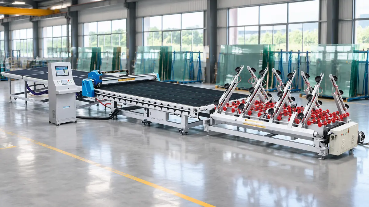
Architectural glazing prioritizes environmental sealing and structural load, but interior glass fixtures face scrutiny under direct spotlighting and human touch. Selecting the appropriate furniture glass processing machinery determines whether a fabricator achieves razor-sharp assembly tolerances or suffers from edge micro-fissures and excessive factory scrap. From delicate 3 mm display cabinet doors to monolithic 19 mm panels intended for tempering into dining surfaces, interior components require mechanical precision that exceeds standard construction glass tolerances. Industrial fabricators require an integrated machinery matrix to process annealed float glass into luxury interior elements while working to reduce micro-flaking and surface scratching as much as the process allows.
Every fabrication step, whether automated scoring, high-gloss flat polishing, or precision hardware cutouts, demands rigid dynamic stability and calibrated pneumatic control. Understanding the operational physics behind these specialized production units allows manufacturing directors to streamline throughput while reducing reliance on expensive manual touch-ups.
Why Furniture Glass Demands a Unique Machinery Architecture
Structural Tolerances vs. Visual Surface Requirements
Architectural facade units conceal their cut edges inside deep structural aluminum mullions or silicone pockets. In stark contrast, furniture applications leave the glass perimeter completely exposed to ambient room light and tactile interaction. A tabletop or an unbacked shelving panel requires an optical edge quality where even microscopic clamshell chips destroy commercial value. Assembly tolerances inside prefabricated metal frames or custom wooden cabinetry leave virtually no margin for dimensional variance.
While a construction cutter may tolerate an error of two millimeters across a long span, furniture joinery binds if dimensions drift beyond fractions of a millimeter. Specialized machinery must balance aggressive cycle speeds with mechanical repeatability to ensure seamless hardware integration.
The Material Spectrum: From 3 mm Cabinet Glass to 19 mm Heavy Table Tops
Interior glass processing encounters an unusually wide spread of material thicknesses within the same working shift. Thin 3 mm to 4 mm float sheets supply lightweight overhead display doors, whereas 15 mm and 19 mm monolithic panels provide heavy structural coffee tables and executive desks. Accommodating this spectrum on a single line requires continuous, fine-tuned adaptation of scoring pressure and breakout mechanics.
Processing thin glass risks spontaneous shatter if tooling pressure creates micro-fractures extending past the median vent depth. Conversely, thick monolithic plates resist clean breakout if the score line fails to penetrate deeply and uniformly across the entire traversal path. Machinery frames must maintain uniform downward force without flexing under substantial variations in tool carriage resistance.
High-Mix, Low-Volume Batch Demands in Modern Interior Production
Some furniture glass fabricators handle mixed custom orders alongside repeat production, processing varying geometric profiles, corner radiuses, and bespoke cutouts within single daily production schedules. Machine operators cannot afford hours of physical retooling between custom dining panels and narrow console inserts. Consequently, the control architecture of modern furniture glass fabrication machinery is generally built to work with factory CAD/CAM nesting data on equipment configured for this purpose.
Cutting bridges, edge polishers, and drilling heads switch toolpaths based on digital cut lists where such integration is in place. This kind of software-driven agility helps prevent production bottlenecks and supports material optimization across high-value raw glass packs.
Core Machinery in the Furniture Glass Processing Workflow
Automated Glass Loading Systems: Mitigating Manual Breakage and Surface Abrasion
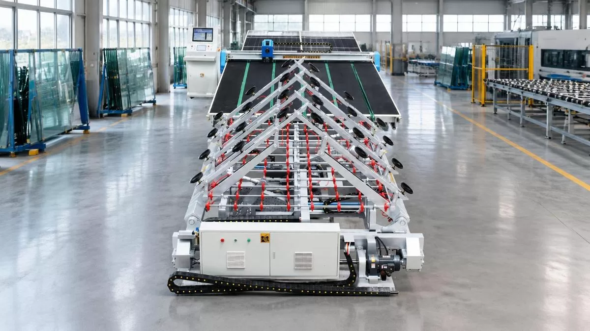
Glass packs arrive at the cutting floor secured on heavy transport racks, where sheet weight and close contact between individual lites make careful handling essential. Manual handling of large jumbo sheets introduces physical hazard, panel deflection, and unavoidable surface scuffs from operator gloves. Automated mechanical loading arms equipped with high-vacuum suction cups bridge this critical intake phase with gentle, consistent handling.
Modern loaders utilize variable-speed drive cycles and pneumatic tilt linkages that approach glass packs at calibrated attack angles. The suction manifold isolates single lites using air-separation blowers, preventing the suction vacuum from dragging adjacent glass lites against each other. Eliminating frictional glass-on-glass contact at raw material intake helps protect surface coatings before fabrication begins.
CNC Glass Cutting Tables: Precision Scoring and Complex Geometric Profiling
The CNC cutting table represents the primary operational hub, converting raw oversized stock into dimensioned profiles. Modern units integrate driven gantry bridges, rotating cutter heads, and pressure-controlled tooling. Rather than merely scribing straight coordinates, these workstations can execute radii, circular table shapes, and internal cutouts, with axis feed rates reaching up to 120 m/min as listed for the YD-CTL series.
Precision scoring demands active mechanical contour following to maintain constant perpendicularity between the carbide cutting wheel and the glass surface. Closed-loop servo motors counteract mechanical backlash on dual-driven longitudinal racks, supporting the cutting precision of ±0.3 mm specified for this equipment. Consistent scoring depth can help reduce subsurface micro-checks, supporting cleaner edge separation during subsequent breakout operations. Actual results still depend on the cutting wheel, glass type, and machine settings in use, so operators should treat the quoted precision as a machine specification rather than a guarantee of defect-free pieces.
Pneumatic and Hydraulic Breaking Tables: Clean Edge Separation Without Micro-Cracks
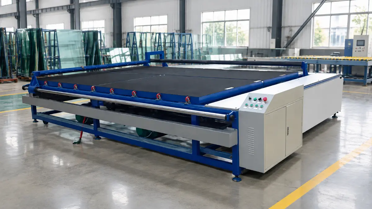
Once scribed, the glass panel advances toward a breakout station engineered to separate cut components along the score lines. The table surface commonly uses an air flotation cushion that reduces contact and friction between the glass and the work surface, making it easier for operators to maneuver heavy stock sheets without scratching the bottom surface.
Pneumatic or hydraulic breakout bars rise beneath the score lines in synchronized sequences. By applying distributed flexural tension from underneath the scribe mark, the mechanical bar propagates the median crack through the glass core. A well-executed breakout can produce a straighter, cleaner edge than a poorly scored or unevenly broken sheet, which in turn can reduce the diamond grinding depth required downstream, though the result still depends on scoring quality and breakout pressure.
Edge Grinding and Polishing Centers: Flat, Pencil, and Beveled Finishes
Raw broken edges feature sharp, micro-flaked perimeters that require profiling before furniture assembly and thermal tempering. Double-edging production lines process parallel rectangular sides in a single pass using staged diamond and resin-bonded polishing wheels. For organic shapes, oval dining tables, or irregular architectural consoles, multi-axis CNC work centers profile edges using continuous interpolation.
Polishing stages progress through coarse diamond removal to eliminate breakout shell marks, transitioning to fine composite wheels for mechanical smoothing. The final station applies cerium oxide or high-grade polyurethane wheels to work toward mirror-finish transparency. In furniture joinery, a polished edge generally looks cleaner and more finished to the eye, but optical clarity on its own does not confirm dimensional straightness, which should be checked against the fabrication drawing or inspection criteria.
Edge grinding works mainly by removing or smoothing out breakout damage and micro-flaws along the perimeter, which can reduce the local weak points that make an edge more vulnerable to mechanical or thermal stress during later handling and tempering.
Precision Drilling, Milling, and Notching for Hardware Integration
Modern architectural cabinetry relies extensively on minimalist hardware, including concealed hinges, UV-bonded pivot mounts, and structural spider fittings. Fabricating these mounting points requires dedicated vertical or horizontal drilling machinery equipped with opposing double spindles. Diamond core drills penetrate the glass simultaneously from upper and lower faces to help prevent breakout spalling on the exit surface.
CNC milling centers simultaneously execute internal corner notches, sink cutouts, and cable pass-throughs using high-speed internal-coolant router bits. Precise water delivery through the tool core flushes abrasive glass slurry away from the cutting interface. Continuous cooling preserves diamond matrix longevity and helps limit localized thermal gradients that can initiate microscopic radial cracks.
Deep Dive into Cutting Line Integration: The Industrial CNC Anchor
Synchronized Three-in-One Workflow: Loading, CNC Cutting, and Breakout
Operating discrete standalone machines creates substantial material staging delays and multiplies manual handling risks throughout the shop floor. Integrated production lines link the loading arms, the CNC cutting table, and the breakout station into a continuous automated cell, so raw stock moves from storage to cut, broken components ready for the edging cell without separate manual transfers between each stage.
Industrial lines like the YD-CTL series demonstrate this type of integrated workflow, combining automatic loading, CNC cutting, and a dedicated breaking table according to the product specification. Engineered by manufacturers such as Liaoda (LAD) Glass Machinery, which traces its fabrication roots back to the 1990s in Foshan, these lines are designed to reduce inter-station manual handling. The product specification lists a working table height of 900±25 mm for the series, which supports physical alignment between the cutting and breakout sections of the line.
Mechanical Rigidity and Vibration Damping: Why Machine Mass Matters
High-speed cutting carriages subject the supporting gantry and structural bed to significant acceleration and deceleration forces during complex geometric profiling. Machine builders generally size the structural frame to resist flexing under these dynamic loads, since excessive movement in the bed can transfer into the cutting wheel and affect scoring consistency. The YD-CTL series lists structural frame weights ranging from 8,000 kg to 12,000 kg across the YD-CTL-4228, 5133, and 6133 models, scaling with the larger glass formats each model is built to handle.
This weight specification reflects the heavy-duty construction described in the product data rather than an independently measured vibration or stiffness result. Stable kinematics support consistent wheel penetration across jumbo format sheets up to 6100×3300 mm, with actual cutting quality also depending on carriage alignment, tooling condition, and maintenance.
Pressure and Feed Control Across the 3 mm to 19 mm Thickness Range
A single fixed setting rarely suits every job when a line alternates between thin display glass and thick tabletop panels in the same shift. CNC cutting equipment in this category typically allows the operator or the control program to adjust cutting pressure and feed speed for the glass thickness being run, which the YD-CTL specification lists as 3 mm to 19 mm. On tighter radiused corners, feed speed is normally reduced to limit tool drift and avoid chipping at the direction change. Straight runs can typically be cut faster once the machine and tooling are set up correctly for the sheet in hand.
Final pressure and speed settings are normally confirmed through trial cuts on the specific glass and tooling in use, since the right combination depends on the wheel, the glass composition, and the condition of the machine rather than a single universal formula.
Layout Planning and Nesting: Reducing Waste on Large-Format Stock Sheets
Raw float glass waste directly erodes operating profit margins in custom furniture fabrication. Many fabricators use nesting software, separate from or alongside the cutting machine, to plan how rectangular door panes, circular tabletop cutouts, and slender shelf elements are arranged on a standard master sheet before cutting begins. Strategic grouping helps minimize trim drop and can shorten the overall cutting path sequence.
A workable layout also needs to leave clear access for the breakout step afterward, since a cutting plan that looks efficient on paper can still create pieces that are difficult to snap apart cleanly if breakout access was not considered. Actual material utilization and throughput gains vary by sheet size, order mix, and plant practice, so fabricators should evaluate these figures against their own production data rather than a general industry figure.
| Technical Specification | YD-CTL-4228 | YD-CTL-5133 | YD-CTL-6133 |
|---|---|---|---|
| Max. Glass Size (mm) | 4200 × 2800 | 5100 × 3300 | 6100 × 3300 |
| Min. Cutting Size (mm) | 100 × 100 | 100 × 100 | 100 × 100 |
| Cutting Precision (mm) | ±0.3 | ±0.3 | ±0.3 |
| Glass Thickness Range (mm) | 3 to 19 | 3 to 19 | 3 to 19 |
| Working Table Height (mm) | 900 ± 25 | 900 ± 25 | 900 ± 25 |
| Max. Cutting Speed (m/min) | 120 | 120 | 120 |
| Total Machine Weight (kg) | 8,000 | 10,000 | 12,000 |
Technical Evaluation Criteria: How to Select the Right Machinery Setup
Specification Matrix: Standalone Cutting Stations vs. Integrated Production Lines
Selecting machinery requires matching capital investment against daily throughput requirements, raw material dimensions, and available shop floor area. While entry-level operations may rely on manually loaded standalone tables, industrial furniture suppliers often require continuous linear processing cells. The following considerations help frame the trade-offs between standalone stations and three-in-one automated production lines; actual throughput, staffing, and waste figures should be calculated against each facility's own sheet sizes, shift patterns, and order mix rather than assumed from generic benchmarks:
-
Assess Daily Sheet Throughput Requirements – Standalone manual cutting tables are generally loaded and positioned by hand, which adds cycle time compared with automated intake. Integrated three-in-one production lines reduce manual staging steps through automated loading, cutting, and breakout, though the resulting daily sheet count depends heavily on glass size, pattern complexity, and shift length.
-
Calculate Breakage and Surface Scrap Costs – Manual sheet handling carries inherent risks of panel drop, corner chipping, and glove-induced surface abrasion. Automated vacuum loading and mechanical roller transfers are intended to reduce handling-related glass waste during primary intake, with the actual reduction depending on glass weight, operator training, and maintenance.
-
Map Floor Plan Allocations and Buffer Zones – Standalone stations require perimeter clearance for manual cart maneuvering, sheet staging racks, and manual breakout tables. Integrated lines consolidate intake, cutting, and breakout into a linear rectangular footprint with continuous material flow.
-
Evaluate Labor Resource Allocation – Standalone stations generally need more hands-on involvement for loading, alignment, and breakout since these steps are performed manually. An automated three-in-one cell shifts much of this work to the control system, though actual staffing levels still depend on shift structure, order complexity, and site safety procedures.
Spindle Dynamics and Coolant Filtration in Downstream Edge Polishing
Downstream edge grinding machinery requires rigorous mechanical assessment, particularly regarding spindle construction and water management systems. Multi-wheel double-edging systems benefit from high-rigidity sealed spindles that limit radial runout under continuous lateral diamond grinding forces. Lateral spindle flutter can transfer onto the glass profile, generating wavy edge profiles that work against optical flat polishing.
Coolant filtration systems influence both diamond tooling life and finished edge clarity. Closed-loop recirculating coolant lines benefit from centrifugal separators or high-volume flocculation tanks to remove microscopic glass swarf. If recirculated water contains abrasive suspended glass particles, the cooling jets can abrade delicate glass surfaces, generating microscopic scratches across polished perimeter bevels.
Factory Footprint, Air Cushion Dynamics, and Material Flow Logistics
An optimized glass fabrication floor coordinates working heights and transfer rates between primary cutting and secondary processing cells. Standardizing working table heights at 900±25 mm, as specified for the YD-CTL series, supports physical coupling with downstream breakout stations, edge-loader conveyors, and washing lines. Misaligned machine heights can force operators to lift or drop sheets, introducing edge impacts that may initiate perimeter fractures.
Air flotation table performance relies on uniform blower pressure and well-maintained surface check valves. When moving 19 mm thick dining plates weighing hundreds of kilograms, weak air cushions can cause the glass to drag across the felt top. Operators should inspect air turbine filters and check valve seals routinely to help maintain smoother flotation across processing tables.
Troubleshooting Edge Defects and Operational Bottlenecks
Root Causes of Edge Chipping During CNC Scoring and Grinding
Edge chipping during breakout often relates to the pairing between the cutting wheel geometry and glass thickness, though the correct wheel angle for a given thickness varies by wheel manufacturer, glass type, and machine settings rather than following one universal figure. As a general tendency, wheels suited to thinner glass are not automatically suited to thick glass, and mismatches can create excess lateral stress instead of clean vertical crack propagation. Fabricators should confirm wheel selection and pressure settings against the cutting wheel and machine manufacturer's process guidance, verifying results with trial cuts on the actual glass thickness in use.
During secondary diamond grinding, perimeter chipping can occur when the machine feed rate exceeds the abrasive removal capacity of the diamond matrix. When diamond wheels become glazed with compacted glass powder, grinding friction increases, which can contribute to small edge chips. Regular dressing of diamond wheels with aluminum oxide dressing sticks helps clear clogged pores and restore smoother cutting action.
Preventing Mechanical Scratching Across Table Transfers
Surface scratching on furniture glass creates immediate visual rejects, particularly on acid-etched, tinted, or low-iron glass varieties. Scratches often trace back to hardened glass debris embedded in the felt work surfaces of cutting and breakout tables. When a heavy sheet slides over embedded swarf, the trapped particle can score the bottom glass surface under the sheet's own weight. Implementing strict preventative cleaning routines helps limit particulate accumulation across transfer surfaces.
Operators should vacuum table felt linings between shifts and wipe down polyurethane transfer rollers daily using clean, lint-free cloths. Maintaining proper air flotation pressure helps sheets float on air cushions rather than abrading against the work table during rotation.
Bridging the Gap to Final Tempering: Edge Integrity and Thermal Fracture Prevention
Thermal tempering can increase resistance to mechanical and thermal stresses and can produce the break pattern required for some safety-glazing applications. The tempering furnace subjects glass to temperatures exceeding 600 degrees Celsius, followed by rapid air quenching that induces high surface compression. If the preceding cold processing machines leave microscopic fissures along the cut edge, the thermal shock of quenching can propagate these flaws, increasing the risk of furnace breakage.
Furniture glass processing machinery that supports consistent scoring and thorough edge finishing helps reduce this risk before glass enters the tempering furnace. High-precision CNC cutting tables, such as those in the YD-CTL series with ±0.3 mm cutting precision, support more uniform score lines, though clean breakout and defect-free edges still depend on correct wheel selection, breakout settings, and thorough downstream grinding. Edge grinding removes or reduces damaged material and edge flaws; the finished edge should still be inspected before tempering.
Frequently Asked Questions (FAQs)
What is the acceptable cutting tolerance for modern furniture-grade glass?
Acceptable tolerances for furniture glass depend on the fabrication drawing, the connecting hardware, and the customer's acceptance criteria, so there is no single figure that applies to every project. The YD-CTL series lists a cutting precision of ±0.3 mm as a machine specification, which fabricators can reference as a baseline when specifying equipment, while final piece tolerances should still be confirmed against the specific joinery and design requirements.
How does glass thickness affect cutting parameters on a CNC line?
Thinner glass generally allows higher feed speeds and lighter downward pressure, while thicker glass in the 12 mm to 19 mm range typically requires slower feed rates and higher pressure to drive the score line deep enough for clean breakout. The exact wheel angle and pressure settings vary by wheel brand and machine, so operators should follow the cutting wheel and equipment manufacturer's guidance and confirm settings with trial cuts rather than relying on a single fixed angle.
Can a CNC glass processing line handle both rectangular cabinet panes and curved organic tabletops?
Some CNC cutting tables, when equipped with a suitable rotating cutter head and compatible control software, can process curved profiles, irregular radii, and straight cuts within the same working envelope. The specific range of shapes a given line can handle depends on its head design, software, and configuration, so fabricators should confirm these capabilities against the equipment and software actually supplied rather than assuming every CNC line offers the same functionality.
What water quality and coolant management is necessary for high-gloss furniture edge polishing?
Edge polishing centers benefit from clean, filtered water with minimal suspended glass swarf. Recirculating coolant systems commonly use multi-stage settling tanks, hydrocyclones, or flocculation units to help remove particulates. Contaminated coolant can dull diamond grinding tools and acts as an abrasive that may scratch polished bevels.
How does machine bed weight relate to cutting stability?
Heavier structural frames, such as the 8,000 kg to 12,000 kg ranges listed for the YD-CTL-4228, 5133, and 6133 models, reflect the heavy-duty construction built for each model's rated glass size. A well-built, adequately rigid frame is generally expected to resist excess flexing during gantry acceleration, though actual vibration performance also depends on installation, leveling, and maintenance rather than frame weight alone.
Conclusion: Strategic Investment in Precision Furniture Glass Machinery
Balancing aesthetic perfection with commercial volume requires equipment engineered specifically for the tight tolerances of modern furniture manufacturing. Heavy-duty machine beds, pressure-controlled cutting tools, and integrated three-in-one production lines are built to support consistent processing from stock intake through breakout. Investing in suitable furniture glass processing machinery, matched to a fabricator's own glass thicknesses, shapes, and volume, helps reduce edge defects and material waste while meeting the practical demands of the interior design and furniture market.
CONTACT US


LIAODA (LAD) Glass Machinery Co., Ltd.
We are always providing our customers with reliable products and considerate services.
If you would like to keep touch with us directly, please go to contact us
-
![Home]()
Home
-
![Tel]()
Tel
-
![Email]()
Email
-
Share
-
![Contact]()
Contact


