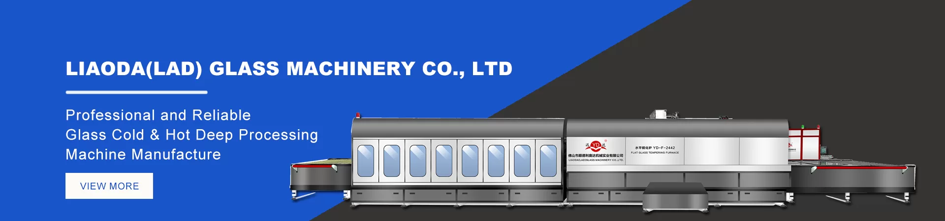
Flat Glass Machinery Guide: Engineering Workflow, Precision Cutting, and Equipment Selection
- By:LiaoDA
- Date:2026-10-21
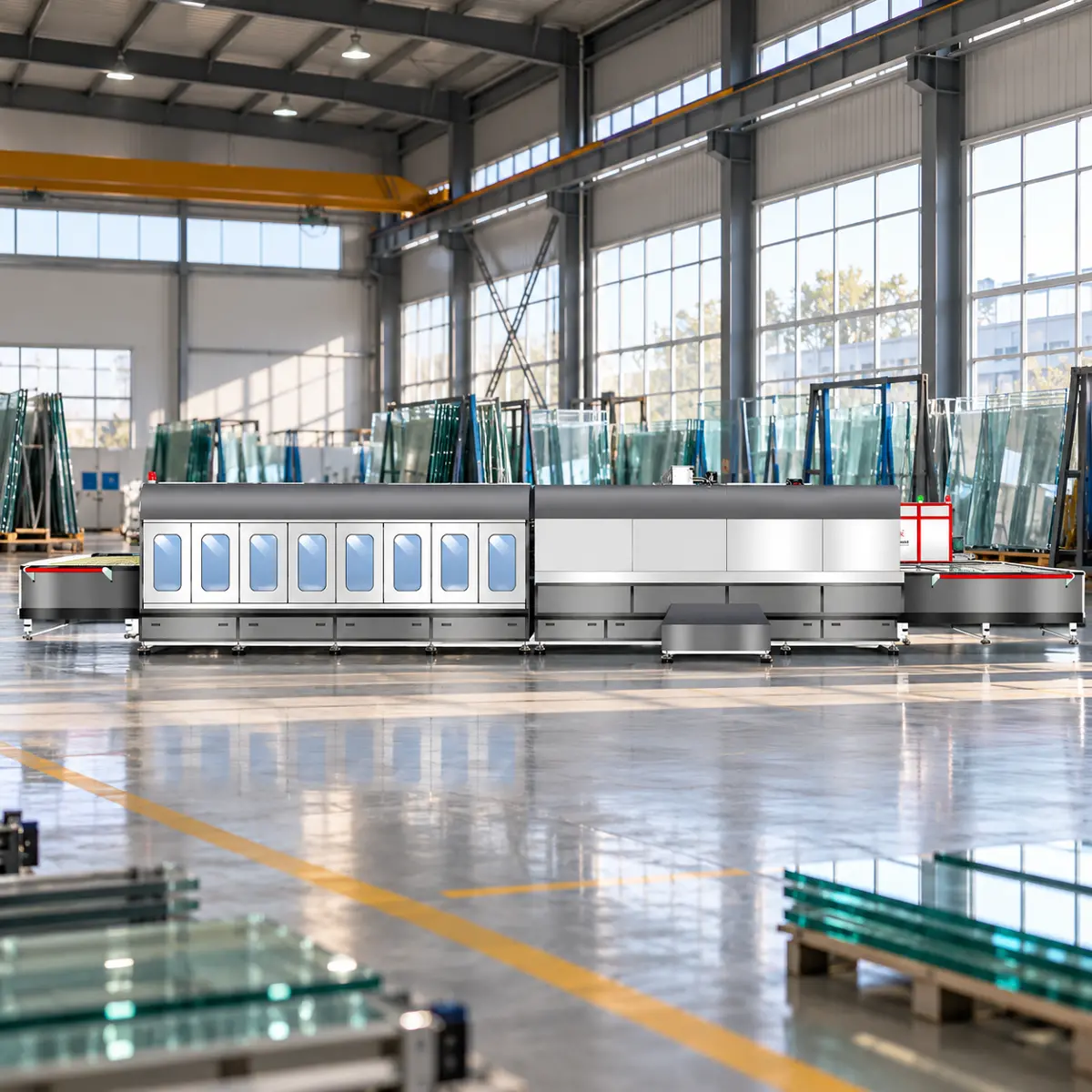
Selecting flat glass machinery determines whether a fabrication plant turns raw float glass into profit or fills cullet hoppers with expensive scrap. When an automated flat glass machinery production line operates with tight mechanical synchronization, every downstream process runs smoothly. Conversely, a fraction of a millimeter of drift at the initial scoring table can increase rework burden, edge chipping risk, and potential thermal breakage inside the tempering furnace. Understanding the mechanical interplay across these processing stations helps plant engineers eliminate hidden bottlenecks before signing a capital equipment contract.
Raw float glass arrives at fabrication facilities as massive, brittle stock sheets that demand careful mechanical handling. Plant managers often assume that upgrading a single downstream station will fix factory-wide yield losses. In reality, flat glass processing behaves like a relay race where the opening runner sets the maximum possible margin for error. By examining how cold processing feeds into thermal treatment, fabricators can configure equipment lines that balance throughput speed with dimensional accuracy.
The Anatomy of a Modern Flat Glass Processing Line
A complete flat glass fabrication floor is divided into two distinct physical regimes: cold processing and hot processing. Because glass is an amorphous solid that fractures when tensile stress concentrates at a flaw, the sequence of machinery follows strict physical laws. Every dimensional alteration must occur while the glass remains in its annealed state, with relatively low residual stress, before heat treatment.
Cold Processing: Loading, Scoring, and Edge Preparation
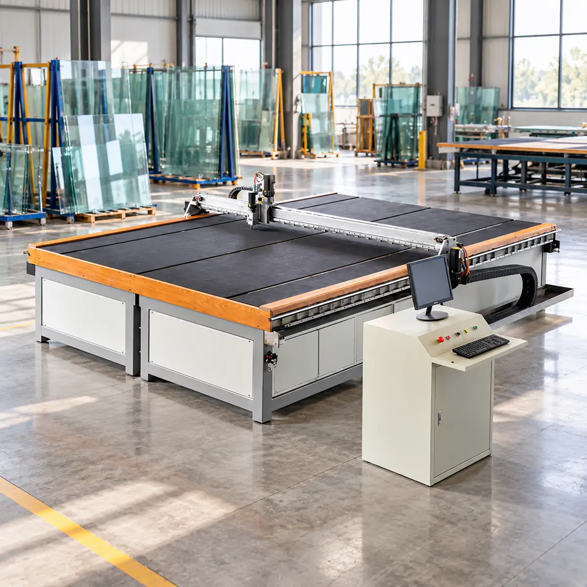
Cold processing encompasses every mechanical operation that shapes raw float glass—typically ranging from 2 mm to 20 mm in thickness—without altering its internal thermal stress profile. Vacuum loading gantries lift raw sheets from storage racks and place them onto cushioned cutting tables. Next, a computer-controlled cutting head inscribes a precise score line across the surface using a hardened wheel, allowing operators or pneumatic bars to snap the glass cleanly along the fissure.
Freshly snapped glass edges are lined with microscopic cracks and sharp irregularities. If left untreated, these micro-fissures act as stress concentrators whenever the lite experiences mechanical bending or temperature shifts. Wet straight-line or CNC edging machines must grind and polish the perimeter, using coolant water to prevent localized frictional heating while removing the damaged boundary layer.
Hot Processing: Thermal Tempering and Structural Integrity
Once cold fabrication is complete, washed glass lites enter the hot processing stage inside a horizontal tempering furnace. Industry practice requires that all cutting, drilling, and edging be completed before heat treatment. Heat-strengthened and fully tempered flat glass, as defined in ASTM C1048, cannot be fabricated after thermal processing. Attempting to score or grind a tempered lite pierces its outer compression layer, releasing stored internal energy and shattering the panel into small cubical fragments.
Inside the furnace, rollers transport the glass through heating zones before blasting both surfaces with high-pressure quench air. This rapid cooling locks the outer surfaces into compression while pulling the core into compensating tension. Fully tempered glass is commonly cited as having about four times the breakage strength of annealed glass of the same thickness. If upstream flat glass machinery leaves an unground micro-crack along the edge, that flaw can compromise strength and increase the risk of breakage during thermal processing.
Why the Cutting Stage Dictates Total Plant Yield
Many fabricators view the cutting table as a simple sizing station rather than a precision machining center. Yet the geometric quality of the initial score dictates the workload of every subsequent machine on the factory floor. When a cutting bridge loses calibration, the entire plant pays a compounding tax in abrasive diamond wear, rejected lites, and wasted furnace energy.
The Hidden Cost of Manual Handling and Inconsistent Scoring
Manual or semi-automatic sheet handling exposes both operators and raw glass stock to severe mechanical risks. Carrying heavy float glass sheets by hand introduces surface scratches and edge impacts before the glass ever touches the felt table. Even minor flexing during manual placement can propagate premature runs across large architectural sheets.
Inconsistent scoring pressure creates an equally costly problem during the breakout stage. If a worn manual cutter applies uneven vertical force, the fracture plane twists away from the vertical axis, leaving a flared edge heel or an undercut bevel. Downstream edging machines must then slow their feed rates and grind away extra millimeters of glass to square the perimeter, burning through diamond wheels and delaying delivery schedules.
Integrated Automation: From Raw Sheet to Broken Lite
Modern high-volume facilities replace fragmented manual stations with a unified CNC glass cutting machine production line that links loading, scoring, and breaking into one continuous cycle. LIAODA (LAD) Glass Machinery Co., Ltd., located in Foshan City, Guangdong Province, China, has developed glass cold and hot processing machines under the Yuanda brand across more than 100 countries and regions. For us, engineering the YD-CTL series meant integrating automatic loading, CNC cutting, and breaking into a single synchronized footprint.
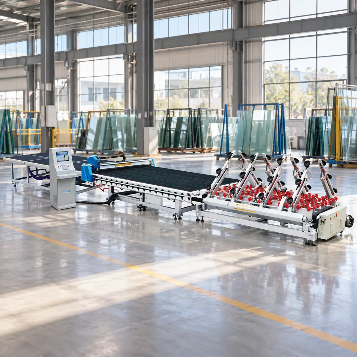
In the YD-CTL production line workflow, the automatic loading system picks raw sheets directly from packs and feeds them onto the CNC cutting table. The numerical control bridge executes complex nested patterns and intricate architectural shapes at maximum cutting speeds of up to 120 m/min. The line is specified to handle glass thicknesses from 3 mm to 19 mm with a cutting precision of ±0.3 mm. Once scored, the sheet transfers smoothly onto a specialized breaking table, reducing manual labor requirements and stabilizing cycle times.
Technical Breakdown: Evaluating CNC Glass Cutting Production Lines
Evaluating industrial flat glass machinery requires looking past brochure headline speeds to examine how structural mass, working envelopes, and dimensional tolerances align with daily production orders. A machine built for thin picture-frame glass will struggle under the inertia of 19 mm structural facade panels. Comparing model specifications side by side clarifies how machine geometry scales with glass dimensions.
Comparing Industrial CNC Cutting Line Configurations
Different plant layouts and stock sheet standards call for distinct table dimensions and structural weights. The table below outlines the verified technical specifications across the three configurations of the Yuanda YD-CTL CNC glass cutting machine production line.
| Technical Parameter | YD-CTL-4228 | YD-CTL-5133 | YD-CTL-6133 |
|---|---|---|---|
| Max. Glass Size (mm) | 4200 × 2800 | 5100 × 3300 | 6100 × 3300 |
| Min. Cutting Size (mm) | 100 × 100 | 100 × 100 | 100 × 100 |
| Cutting Precision (mm) | ±0.3 | ±0.3 | ±0.3 |
| Glass Thickness Range (mm) | 3 ~ 19 | 3 ~ 19 | 3 ~ 19 |
| Working Table Height (mm) | 900 ± 25 | 900 ± 25 | 900 ± 25 |
| Max. Cutting Speed (m/min) | 120 | 120 | 120 |
| Machine Weight (kg) | 8000 | 10000 | 12000 |
Critical Mechanical Metrics Beyond Top Speed
While a 120 m/min maximum cutting speed indicates rapid gantry travel, sustained accuracy depends on how the physical frame handles rapid acceleration and deceleration forces. Buyers inspecting flat glass machinery should evaluate four underlying mechanical design factors:
- Structural Mass and Specification Verification: The YD-CTL models are listed at weights between 8,000 kg and 12,000 kg, with a stated cutting precision of ±0.3 mm. Buyers should verify rigidity, repeatability, and service-life claims through manufacturer documentation or acceptance testing rather than relying on headline specifications alone.
- Gantry Rail and Drive Configuration: Precision linear guide rails and protected cabling are standard features that help keep the cutting bridge aligned to the table axis. Buyers should request details on rail specifications and maintenance requirements to assess long-term performance.
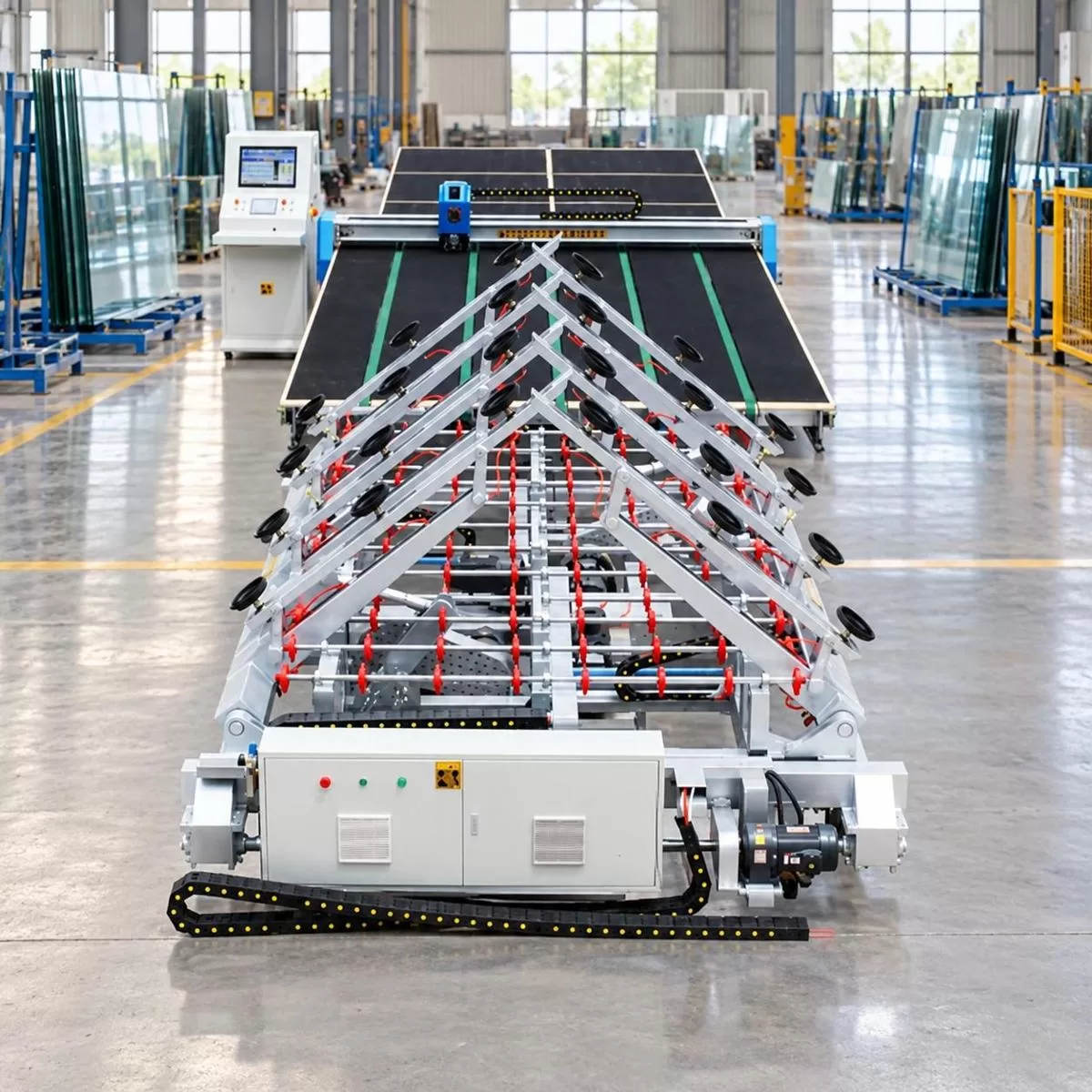
- Automatic Loading System: The YD-CTL series includes an automatic loading system designed to handle the specified glass thickness range. Reliable vacuum distribution and mechanical coordination prevent sheet slippage during the loading cycle.
- Ergonomic Table Height Standardization: Maintaining a consistent working table height of 900 ± 25 mm aligns the cutting line with downstream breaking tables and edging conveyors, reducing operator strain during manual breakout of small 100 × 100 mm pieces.
Step-by-Step Decision Framework for Selecting Flat Glass Machinery
Purchasing capital equipment without mapping out upstream supply constraints and downstream capacity often creates expensive floor bottlenecks. A cutting line that outpaces the edging department by three to one simply stacks vulnerable, unground glass racks across valuable factory aisles. Engineering teams can avoid mismatched equipment by following a structured evaluation sequence.
Auditing Your Glass Thickness and Order Mix
Before requesting quotes for flat glass machinery, plant managers need an honest audit of their product mix over a typical production quarter. Facilities supplying curtain wall contractors process large-scale construction components in 10 mm to 19 mm thicknesses, requiring careful evaluation of table size to handle jumbo float stock. Conversely, shops producing interior mirrors, appliance panels, or fine artistic glass pieces frequently cut 3 mm to 6 mm sheets down to 100 × 100 mm minimum dimensions.
Because the YD-CTL architecture spans the 3 mm to 19 mm thickness range and executes intricate CNC patterns, a single line can bridge architectural and decorative workloads. Buyers must verify that their warehouse cranes and floor slabs can support both the machine footprint and the accompanying packs of raw glass.
Five-Step Procurement and Floor Integration Checklist
To translate production goals into a reliable machinery layout, procurement engineers should execute the following five-step decision process:
- Standardize Raw Stock Sheet Dimensions: Measure the exact float glass pack sizes delivered by your regional suppliers and select a cutting bed—such as 4200 × 2800 mm, 5100 × 3300 mm, or 6100 × 3300 mm—that accommodates your largest stock sheet without overhang.
- Match Cutting Tolerances to Edging Allowances: Confirm that the cutting line holds the required accuracy so downstream CNC edgers and double-edging lines can process the glass within their capabilities. Verify grinding allowances and spindle limits with your edger and equipment suppliers.
- Synchronize Tact Times Across Cold and Hot Zones: Calculate how many square meters per hour the 120 m/min CNC cutting line yields after nesting optimization, ensuring your washing machines and tempering furnaces can absorb that volume without staging bottlenecks.
- Verify Structural Floor Load and Pneumatic Utilities: Check that your concrete slab meets the static and dynamic load requirements for an 8,000 kg to 12,000 kg line, and supply clean, dry compressed air for the pneumatic loading arms.
- Test CAD/CAM Nesting and Control Console Integration: Ensure the operator control station imports standard DXF files and ERP cutting lists seamlessly, minimizing idle time between batch changes.
Operational Best Practices for Long-Term Machine Accuracy
Even the heaviest industrial flat glass machinery will drift out of specification if preventative maintenance is neglected in a harsh, silica-dust environment. Microscopic glass splinters and airborne grinding mist act like liquid sandpaper inside unprotected mechanical joints. Establishing disciplined daily calibration routines preserves first-day tolerances across years of multi-shift operation.
Calibration of Gantry Bridges and Cutting Heads
Maintaining ±0.3 mm cutting precision requires matching cutting wheel geometry and pneumatic downward pressure to the exact thickness of the float glass sheet. Thin 3 mm glass demands a sharper wheel angle and lighter scoring pressure to prevent crushing the surface, whereas 19 mm structural plate requires a wider wheel angle and higher pressure to drive a deep vertical median crack.
Operators should inspect tungsten carbide or diamond cutting wheels at every shift change, replacing any wheel that leaves a white, powdery crush trail instead of a clean, translucent score line. Linear guide rails and rack-and-pinion drives on the gantry bridge also require daily cleaning. Accumulated glass cullet on a precision rail forces the cutting head upward by fractions of a millimeter as it passes, creating un-scored skips that ruin the breakout phase.
Synchronizing Pneumatic Loading and Breaking Table Condition
Reliable sheet transfer depends on the mechanical health of the loading arms and breaking surfaces. Maintenance teams must inspect the rubber suction cups on the loading frame weekly for embedded glass shards or perished perimeter seals. A single leaking cup reduces vacuum grip, risking catastrophic sheet drops during the lift cycle.
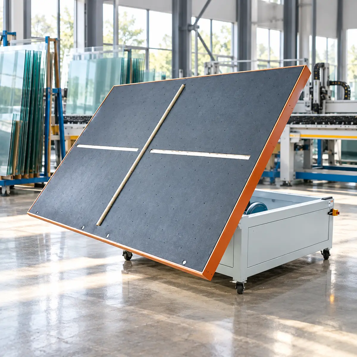
Similarly, the felt work surface on cutting and tilting breaking tables must be brushed free of cullet between cycles and kept level according to the manufacturer's installation and maintenance requirements. When a scored sheet transfers for manual or automated snapping, a clean, flat felt bed ensures bending force applies solely along the score line rather than fracturing across a trapped glass splinter.
Frequently Asked Questions About Flat Glass Machinery
What is the standard cutting tolerance for industrial CNC flat glass machinery?
The YD-CTL series lists ±0.3 mm cutting precision as its specification, which reflects the design capability of this production line. Required and achievable tolerances vary significantly by machine design, process control, calibration maintenance, and job requirements. Buyers should verify that a cutting line's stated tolerance aligns with their downstream edging and assembly needs, and confirm the tolerance under their specific operating conditions rather than relying on headline specifications alone.
Can a single CNC glass cutting line process both thin decorative glass and thick structural glass?
Yes, versatile production lines such as the Yuanda YD-CTL series are built to process glass thicknesses ranging from 3 mm up to 19 mm on the same bed. Glass fabrication practice often requires adjustments to cutting wheel selection and scoring pressure to match sheet thickness and glass type. Facilities can switch between delicate 100 × 100 mm artistic lites and heavy architectural panels by following the manufacturer's operating guidance for thickness-specific settings, allowing a single line to bridge architectural and decorative workloads.
Why must flat glass edging and cutting be completed before thermal tempering?
Thermal tempering heats glass and rapidly quenches it with high-pressure air, locking the outer surfaces into high compression and the core into tension. Cutting or grinding tempered glass penetrates the protective compression zone and releases internal tensile stress, causing the entire sheet to shatter instantly. Industry practice requires that all fabrication that changes the glass geometry or introduces edge stress be completed before heat treatment. This sequence is fundamental to glass processing because the compression layer created during tempering makes the material permanently unworkable with conventional cutting and grinding tools.
How do I choose between a 4200 mm, 5100 mm, and 6100 mm glass cutting line?
Your choice between models like the YD-CTL-4228 (4200 × 2800 mm), YD-CTL-5133 (5100 × 3300 mm), and YD-CTL-6133 (6100 × 3300 mm) depends on the standard raw float glass stock sizes available in your market and your maximum architectural order dimensions. Facilities whose stock sheets or orders exceed the smaller models' working dimensions may need the 6100 × 3300 mm platform and a floor rated for its 12,000 kg weight, while regional shops processing medium stock sizes can optimize floor space with the 8,000 kg YD-CTL-4228. Verify that your material-handling equipment, building crane capacity, and floor structural rating can accommodate both the machine footprint and the raw glass packs you intend to process.
Building a High-Yield Glass Fabrication Floor
Profitability in glass fabrication rarely comes from running individual machines at reckless speeds. It comes from eliminating waste between stations. When an integrated CNC glass cutting machine production line delivers accurately cut lites to the edging and tempering departments, and when downstream capacity is coordinated with upstream output, cutting-related scrap can be reduced and production flow stabilized. Evaluating flat glass machinery through the lens of structural specifications, stated dimensional precision, and automated material handling gives plant managers a foundation for building reliable, efficient production systems.
CONTACT US


LIAODA (LAD) Glass Machinery Co., Ltd.
We are always providing our customers with reliable products and considerate services.
If you would like to keep touch with us directly, please go to contact us
-
![Home]()
Home
-
![Tel]()
Tel
-
![Email]()
Email
-
Share
-
![Contact]()
Contact


