Glass Magnesium Board Machinery and Architectural Glass Processing: A Dual-Line Planning Guide
- By:LiaoDA
- Date:2026-10-28
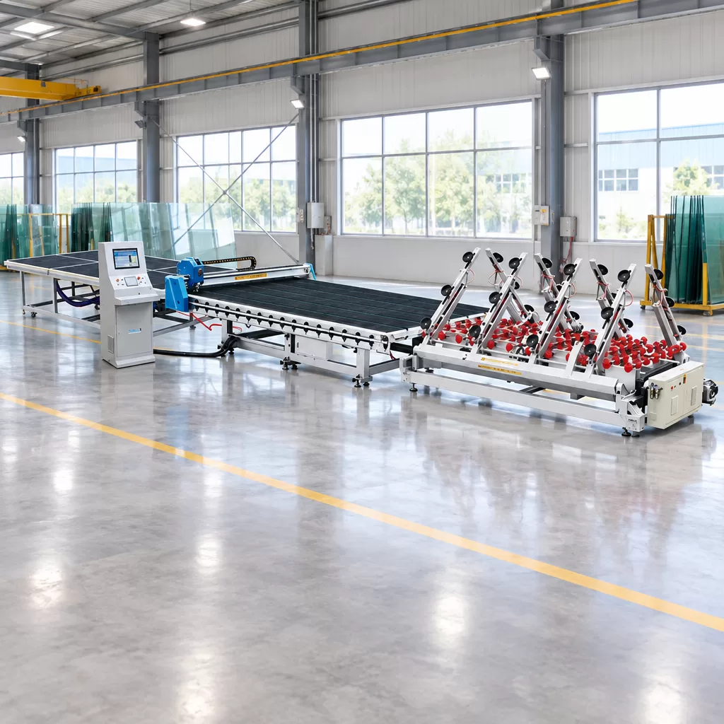
Sourcing glass magnesium board machinery means acquiring equipment that forms fire-rated magnesium oxide composite boards through wet-slurry casting, reinforcement layup, and controlled curing. Plant directors setting up an MgO board production facility should recognize that this equipment category is entirely separate from the precision glass cutting lines used to prepare architectural glazing. Understanding this distinction prevents costly specification errors when planning factories that produce both substrate panels and glass-based assemblies, since each material requires dedicated processing equipment.
A manufacturer producing modular wall panels may need both MgO board forming systems and separate flat-glass processing equipment if their product portfolio includes glazed partitions. Clarifying the mechanical boundary between composite board extrusion and architectural glass cutting allows plant engineers to build integrated facilities that handle diverse product lines efficiently, with each material routed through the appropriate production line.
Understanding Glass Magnesium Board Machinery in Modern Construction
Before signing equipment contracts, procurement engineers should clarify which material processes their factory actually requires. The term glass magnesium board machinery refers specifically to the equipment that forms MgO composite panels, not the flat-glass cutting systems used to prepare architectural glazing. Each equipment category serves a distinct manufacturing process and material type.
The Chemistry and Mechanics Behind MgO Board Manufacturing
Despite its common commercial name, a glass magnesium board contains no molten float glass. Instead, the substrate is an inorganic composite synthesized from calcined magnesium oxide powder reacted with an aqueous solution of magnesium chloride or magnesium sulfate. Manufacturers reinforce this cementitious slurry with layers of alkali-resistant fiberglass mesh, non-woven fabric, and lightweight fillers such as perlite or wood fiber, building up a layered structure during the forming process. The chemical reaction forms a magnesium oxychloride or oxysulfate crystal matrix that provides the finished board's fire-resistance and structural properties.
Equipment exposed to concentrated brine solutions during mixing and forming may experience accelerated corrosion depending on material selection and exposure conditions. MgO board making machines may incorporate corrosion-resistant components such as stainless steel vessels, polymer formwork, and calibrated compression rollers designed to expel trapped air pockets before crystallization begins. The specific material grades, equipment configuration, and corrosion-resistance measures vary by equipment supplier and should be confirmed before purchase.
Why Separate Equipment Categories Matter for Project Planning
Flat glass processing equipment enters factory planning conversations when a manufacturer's product portfolio extends beyond bare MgO boards. Some modular panel systems incorporate MgO boards as structural components alongside architectural glass elements such as observation windows or decorative cladding. In these cases, a facility needs both composite board forming lines and separate glass cutting systems to cover the full product range, with each material processed on dedicated equipment designed for its specific physical properties.
If a panel manufacturer produces assemblies requiring precision-cut glass components, dimensional control becomes critical for efficient downstream assembly. Manual glass cutting introduces variance that can affect assembly fit. Manufacturers producing high-volume architectural panel systems often install dedicated automated glass cutting lines to maintain consistent part geometry throughout production runs, which reduces rework and simplifies downstream assembly planning.
Core Equipment Stages in MgO Board Forming Systems
Producing dimensionally stable composite boards requires mechanical control over slurry chemistry, reinforcement placement, and curing conditions. Board forming processes vary significantly by manufacturer and formulation. The following stages represent approaches that some production lines may use, though equipment design, specific configurations, process parameters, and curing schedules must be confirmed with the selected line supplier since different formulations and manufacturers employ different systems.
Raw Material Metering and Slurry Mixing Systems
Consistency in MgO board production typically starts with careful batching of raw materials. Some production lines use load-cell hoppers to weigh calcined magnesia powder, perlite, and modifier additives, while the molar ratio between magnesium oxide and brine affects the final board's physical properties and long-term stability. Automated dosing systems may measure liquid brine density before discharging the solution into mixing equipment, and this metering step can contribute to batch-to-batch repeatability when properly calibrated and maintained.
Once inside the mixing chamber, blades fold the dry powders into the liquid phase. The mixing intensity must be sufficient to create a homogeneous paste without entraining excessive air, since trapped air bubbles can act as structural weak points during the board's subsequent curing and trimming stages. Operators typically rely on the mixer manufacturer's recommended settings and batch timing to achieve proper slurry consistency for the specific formulation being produced.
Reinforcement Layup and Extrusion
After mixing, the slurry flows onto rigid templates or continuous belts depending on the line design. Some systems apply a release agent before the primary slurry distributor lays down the base coat, while others may use alternative release methods. Production lines may incorporate systems that unwind alkali-resistant glass fiber mesh and non-woven fabric directly into the wet matrix according to the reinforcement schedule, building up the layered structure that gives the finished board its mechanical strength and dimensional stability.
The layered assembly then passes beneath extrusion rollers or compression plates depending on the line configuration. Vibration or compression forces the slurry to penetrate the reinforcement layers while expelling trapped air, though the specific mechanisms vary by equipment design. Board thickness, width capacity, and production speed depend on the specific equipment model and must be verified with the machinery supplier before a line is specified for a given product mix.
Curing, Demoulding, and Edge Finishing
Freshly formed wet boards require controlled curing to develop mechanical strength. Curing protocols vary significantly by formulation and manufacturer, with some systems using ambient or moderately heated primary curing followed by extended secondary curing that may last days or weeks. Temperature profiles, humidity control, and total curing duration must be confirmed with the board chemistry supplier and equipment manufacturer, since these parameters directly affect the finished board's dimensional stability and can differ substantially between production systems.
Once sufficient set strength is achieved, boards are separated from their carrier templates or belts through demoulding operations that vary by line design. Final processing typically includes edge trimming using diamond or carbide blades equipped with dust collection systems, bringing the boards to the dimensional tolerances required for their intended applications and downstream assembly work. These finishing steps ensure that boards meet the geometric specifications needed for installation or further processing.
Architectural Glass Processing for Panel Assembly Integration
Manufacturers producing architectural panels that incorporate both MgO substrates and glass components operate two distinct production workflows. After MgO boards complete their forming and curing cycle, they may enter assembly lines where they are combined with other materials. If the final product includes glass observation windows, decorative glazing, or glass cladding, those glass components are typically prepared on separate flat-glass processing equipment designed specifically for scoring and breaking architectural glass rather than forming composite panels.
Dimensional Requirements in Multi-Material Panel Assembly
Consider a partition assembly where a glass window module sits inside a pre-routed frame alongside MgO panel sections. The fit between glass edges and frame channels depends on cumulative dimensional control across multiple components, with tolerances stacking up through the complete assembly. If cut glass dimensions vary significantly from part to part, assembly becomes difficult and sealing performance may be compromised, requiring rework or manual adjustment that slows production and increases labor costs.
Decorative architectural wall systems may also bond glass sheets onto fire-rated backing boards. When glass cladding and substrate panels share common reference edges or mounting planes, maintaining consistent part geometry across production runs supports efficient assembly and uniform appearance, which is one reason some panel producers choose to standardize on a single glass cutting line rather than outsourcing that step to multiple suppliers with varying equipment and tolerance capabilities.
Automated Glass Cutting Systems for Architectural Applications
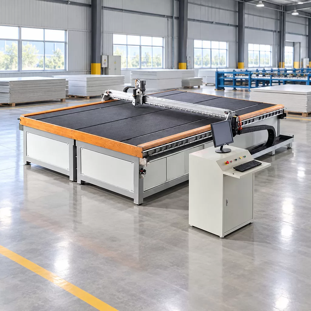
To support consistent part geometry in architectural glass applications, LIAODA (LAD) Glass Machinery Co., Ltd., headquartered in Foshan City, Guangdong Province, China, manufactures the CNC Glass Cutting Machine Production Line YD-CTL under our Yuanda brand. Having produced glass processing equipment since the 1990s for clients across more than 100 countries and regions, for us, flat-glass processing reliability centers on integrating sheet handling, precision scoring, and controlled breaking into a continuous workflow that reduces manual handling and supports repeatable part production.
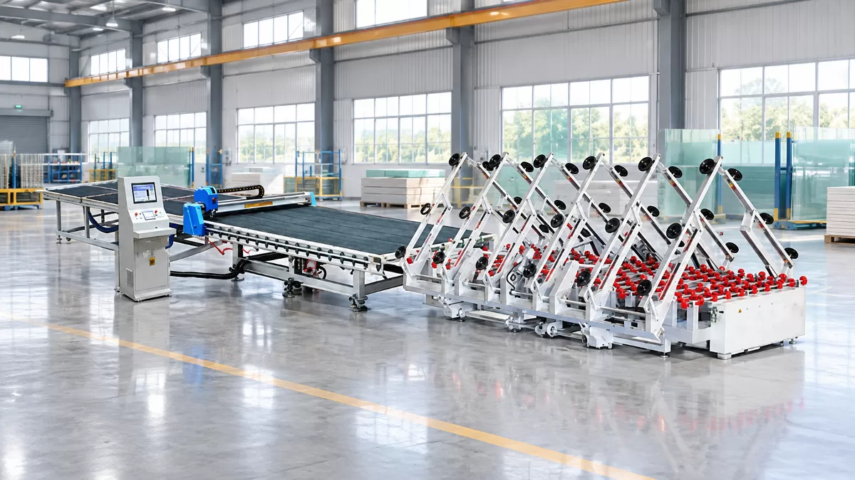
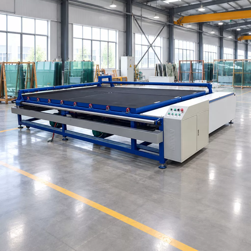
The YD-CTL series is designed for high-precision industrial glass cutting, integrating automatic loading, a CNC cutting table, and a specialized breaking table according to the manufacturer's specifications. The automatic loading system transfers raw float glass sheets onto the CNC cutting table, reducing manual handling effort and the associated risk of edge damage. Once positioned, the overhead gantry bridge executes cutting patterns according to programmed toolpaths, with the manufacturer specifying a maximum cutting speed of 120 m/min and a cutting precision of ±0.3 mm as separate performance parameters. Buyers should confirm with the supplier how the precision figure is measured, under what conditions, and whether both specifications apply simultaneously during actual production.
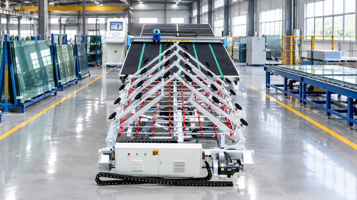
The CNC head can execute both linear cuts and complex contours on glass thicknesses from 3 mm to 19 mm as specified by the manufacturer, covering the range typically used in architectural panel assemblies. After scoring, sheets advance to a specialized breaking table set at a working height of 900±25 mm, where operators separate finished pieces following the score lines through controlled manual or mechanical breaking operations that complete the cutting process.
Technical Comparison of YD-CTL Series Models
Selecting the appropriate glass cutting line configuration depends on the maximum sheet dimensions used in your production and daily throughput requirements. Below is the manufacturer-supplied engineering parameter comparison across the three standard YD-CTL configurations.
| Technical Parameter | YD-CTL-4228 | YD-CTL-5133 | YD-CTL-6133 |
|---|---|---|---|
| Max. Glass Size (mm) | 4200 × 2800 | 5100 × 3300 | 6100 × 3300 |
| Min. Cutting Size (mm) | 100 × 100 | 100 × 100 | 100 × 100 |
| Cutting Precision (mm) | ±0.3 | ±0.3 | ±0.3 |
| Glass Thickness Range (mm) | 3 ~ 19 | 3 ~ 19 | 3 ~ 19 |
| Working Table Height (mm) | 900 ± 25 | 900 ± 25 | 900 ± 25 |
| Max. Cutting Speed (m/min) | 120 | 120 | 120 |
| Total Machine Weight (kg) | 8000 | 10000 | 12000 |
Step-by-Step Selection Framework for Factory Engineers and Buyers
Investing in heavy industrial equipment requires aligning mechanical capabilities with concrete building constraints and downstream processing requirements. Plant engineers planning facilities that produce both composite panels and architectural glass assemblies can follow a structured decision sequence to help prevent capacity mismatches between different production stages.
Evaluating Facility Layout, Power Supply, and Throughput Targets
-
Audit your product portfolio to identify which items require MgO board forming equipment and which require flat-glass cutting systems. Ensure dust-generating composite board saws are physically isolated from clean glass scoring tables to prevent cross-contamination.
-
For glass cutting equipment, calculate the maximum raw sheet dimensions used in your production contracts and inventory planning. Consider the YD-CTL-4228 for sheets up to 4200×2800 mm or scale to the YD-CTL-6133 for jumbo 6100×3300 mm glass depending on your typical order specifications.
-
Verify concrete slab load ratings across installation bays, accounting for static machine weights ranging from 8,000 kg to 12,000 kg depending on model, plus dynamic material storage loads from glass racks and board stacks in adjacent work zones.
-
For facilities producing multi-material assemblies, synchronize cycle times between board forming, glass cutting, and final assembly stations to prevent bottlenecks or idle equipment that reduces overall facility throughput and labor efficiency.
-
Confirm electrical supply conditions against the equipment manufacturer's installation manual for each machine, and separately verify compressed air quality specifications only for those subsystems that are actually pneumatically driven, such as vacuum suction loaders or pneumatic clamps, rather than assuming all equipment shares identical utility requirements.
Matching Equipment Specifications to Production Requirements
When reviewing technical proposals from machinery builders, consider how published specifications translate to practical production capabilities in your specific application:
-
Cutting Precision: The manufacturer lists a cutting precision of ±0.3 mm for the YD-CTL series. This figure describes the published equipment specification rather than a confirmed positioning-accuracy value or a guarantee of repeatable part dimensions across a production run. Buyers should ask the supplier how the value is measured and under what conditions before relying on it for downstream tolerance planning.
-
Structural Mass: The YD-CTL models carry manufacturer-listed weights ranging from 8,000 kg on the YD-CTL-4228 to 12,000 kg on the YD-CTL-6133. These figures are useful for floor-loading calculations and facility planning. The supplier can clarify how the frame design relates to the machine's operating performance.
-
Material Range: A 3 mm to 19 mm thickness range covers common architectural glazing applications from thin decorative panels to thicker structural glass, allowing a single cutting line to handle diverse product specifications.
-
Integrated Automation: Combining loading, cutting, and breaking functions on a single platform is intended to streamline material flow compared to separate manual stations, reducing labor requirements and material handling time between process steps.
Operational Maintenance and Quality Control Best Practices
Production lines require consistent maintenance to preserve accuracy and throughput over their operating lifetime. Facilities housing both composite board forming equipment and precision glass cutting systems must address the distinct maintenance requirements of each process, since the two equipment categories face different wear mechanisms and contamination sources.
Maintaining Board Forming Equipment
On MgO board forming lines, hardened slurry buildup on mixing vessels and extrusion rollers can affect board consistency by creating uneven material distribution or surface defects. Regular cleaning of mixing chambers, metering equipment, and forming templates helps maintain process control and prevents progressive thickness variation as residue accumulates. The specific cleaning intervals and procedures depend on the formulation chemistry and equipment design, so operators should follow the schedule recommended by their line supplier rather than a generic timetable that may not account for the specific brine concentration or filler materials in use.
Trimming saws that cut cured MgO boards generate alkaline dust containing magnesium compounds and mineral fillers. Maintaining dust collection systems and replacing filters on schedule protects both worker health and nearby equipment from particulate contamination, and it also helps prevent dust migration into adjacent glass processing areas where surface contamination would require additional cleaning steps and could compromise optical quality or adhesive bonding in downstream assembly operations.
Maintaining Glass Cutting Systems
Precision glass cutting requires care of pneumatic, mechanical, and cutting subsystems to maintain the published accuracy specifications over time. Technicians should inspect vacuum suction components for wear or contamination that could affect sheet handling reliability, checking hose connections and suction cup condition at the start of each shift to catch deterioration before it causes sheet slippage or misalignment during transfer operations.
Along CNC gantry bridges, linear guideways and drive mechanisms should be kept clean and properly lubricated according to the manufacturer's maintenance schedule. Operators should monitor cutting wheel condition and verify that lubrication systems deliver consistent film to the cutting path, since inadequate lubrication or worn wheels can produce poor-quality score lines that lead to uncontrolled breaking. Air systems supporting breaking tables require clean intake filters to maintain proper operation, and routine filter checks help avoid uneven air support during the breaking step that could cause irregular fracture propagation or edge quality problems.
Frequently Asked Questions About Glass Magnesium Board Machinery
Does glass magnesium board machinery cut both MgO boards and architectural float glass?
No, these are separate equipment categories serving distinct manufacturing processes. Glass magnesium board machinery refers specifically to equipment that creates composite panels through wet-slurry casting, reinforcement layup, and controlled curing, while trimming cured boards typically requires diamond or carbide saws with dust extraction systems designed for abrasive composite materials. Architectural flat glass processing uses different equipment such as CNC scoring and breaking systems that apply controlled surface stress to initiate and propagate cracks in brittle glass rather than sawing through fibrous composites. A facility producing both material types would typically install dedicated equipment for each process.
What thickness ranges do board forming lines and glass cutting lines handle?
Board thickness capacity depends on the specific forming equipment model and formulation chemistry, since different binder systems and reinforcement schedules produce boards with different density and thickness profiles. Equipment suppliers can confirm the thickness range and width capacity for their systems based on roller spacing, template depth, and curing chamber dimensions. For flat glass cutting, the YD-CTL series handles sheets from 3 mm to 19 mm thick according to the manufacturer's specifications, covering the range typically used in architectural applications.
How does cutting precision affect panel assembly?
The YD-CTL series carries a manufacturer-listed cutting precision of ±0.3 mm. This published figure describes the equipment specification rather than a verified positioning-accuracy value or a guarantee of repeatable part dimensions across a production run under all operating conditions. Final assembly fit and sealing performance depend on the complete system, including frame tolerances, gasket design, glass edge finishing, installation procedures, and project-specific requirements. Manufacturers should confirm with the supplier how the precision figure is measured, then design and verify assemblies against their own performance targets using tolerance stack-up analysis.
How much floor space and structural support does automated glass cutting equipment require?
Floor requirements depend on the model selected and the facility's specific installation conditions. The YD-CTL-4228 processes sheets up to 4200×2800 mm and weighs 8,000 kg, while the YD-CTL-6133 handles sheets up to 6100×3300 mm and weighs 12,000 kg. Facility engineers should verify actual floor load capacity against the specific model's weight, footprint, and load distribution, along with storage and dynamic handling loads from adjacent material staging areas, and should follow the manufacturer's installation requirements to ensure proper structural support rather than assuming a fixed slab specification applies universally.
Conclusion: Planning Facilities for Diverse Product Portfolios
Manufacturers producing architectural panel systems must first clarify which equipment categories their product portfolio requires. Glass magnesium board machinery refers specifically to the equipment that forms MgO composite panels through wet-slurry processing, while flat-glass processing equipment such as CNC cutting lines serves a separate function in preparing architectural glazing components. A facility producing only composite boards needs board forming equipment. A facility producing assemblies that incorporate both composite substrates and precision-cut glass components would install separate systems for each material, routing each through dedicated production lines designed for its specific processing requirements.
By understanding that glass magnesium board machinery and architectural glass cutting lines are distinct equipment categories serving different manufacturing processes, plant engineers can specify the appropriate systems for their production requirements. Whether scaling up composite board forming capacity or adding flat-glass processing capability for multi-material assemblies, matching equipment specifications to actual production needs supports efficient facility operation and product quality.
CONTACT US


LIAODA (LAD) Glass Machinery Co., Ltd.
We are always providing our customers with reliable products and considerate services.
If you would like to keep touch with us directly, please go to contact us
-
![Home]()
Home
-
![Tel]()
Tel
-
![Email]()
Email
-
Share
-
![Contact]()
Contact


