The Engineering Mechanics Behind Automated Feeding in Flat Glass Processing Lines
- By:LiaoDA
- Date:2026-09-09
Handling raw float glass at an industrial scale presents a unique set of physics problems. The sheer mass of a jumbo architectural panel demands precise, calculated control. Dropping or mishandling a sheet compromises the entire production schedule.
Modern glass machinery solves this fundamental material handling problem through rigid mechanical automation. Relying on manual labor to feed edging or washing lines is no longer viable for high-volume facilities. The physical strain on human operators naturally introduces unpredictable variables into the workflow.
When a factory needs to move flat glass from storage racks to processing lines, the transition must be seamless. Any hesitation or misalignment during the feed cycle causes downstream bottlenecks. The loading machine serves as the primary gateway for this entire manufacturing ecosystem.
By replacing unpredictable manual handling with programmable kinematics, facilities can establish a reliable baseline for their daily throughput. We will examine the specific mechanical principles that make this automated feeding process both safe and highly efficient.
The Physics of Vacuum Pressure Distribution
Glass is incredibly dense and inherently brittle under uneven mechanical stress. A panel measuring 3300 by 6000 millimeters at a thickness of 19 millimeters weighs approximately 940 kilograms. You cannot simply lift a sheet of this magnitude without inducing severe central deflection.
To counteract gravity and material bending, the lifting mechanism must distribute its hold points evenly. The system achieves this by utilizing a network of negative pressure zones across the glass surface.
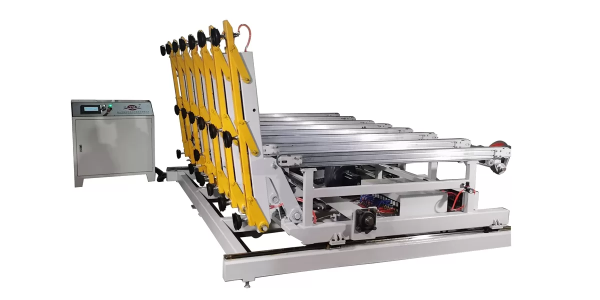
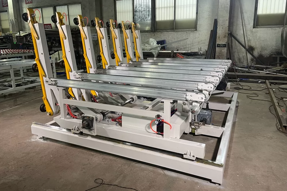
The loading machine distributes the physical load across five or seven articulated lifting arms. Each individual arm features either three or four independent suction cups. This creates a geometric grid of holding force that supports the fragile substrate during elevation.
Vacuum generation must remain consistent across all operational cups. If a single zone experiences a pressure drop, the surrounding cups must possess enough redundant holding force to prevent a catastrophic drop. The layout ensures that tension is dispersed away from the vulnerable edges of the glass sheet.
When handling thinner substrates, such as three-millimeter furniture glass, the physics change entirely. The machine must apply enough vacuum to secure the sheet without pulling the thin glass into the suction cup housing. The pneumatic controls modulate this pressure based on the specific material profile loaded via the interface.
Kinematics of the Articulated Lifting Sequence
Moving massive glass sheets requires deliberate acceleration and deceleration profiles. The working speed of this equipment ranges from three to six pieces per minute. While this cycle time might seem conservative, it is dictated by the laws of inertia.
Jerky or sudden mechanical movements would instantly snap the vacuum seal. Rapid acceleration could also cause micro-fractures within the internal structure of the glass. The integrated 7.5-kilowatt motor provides exactly enough steady torque to manage these shifting loads smoothly.
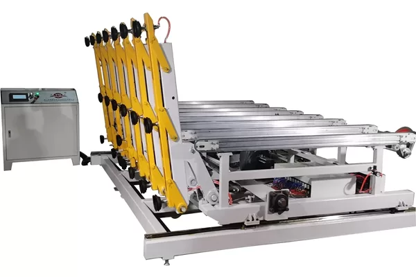
The yellow mechanical arm linkages operate through a synchronized tilting sequence. As the arms rotate from a near-vertical pickup position to a horizontal drop-off angle, the center of gravity constantly shifts. The hydraulic or pneumatic actuators must dampen this kinetic energy before the glass reaches the conveyor bed.
The structural frame of the machine plays an active role in this kinetic sequence. High-frequency vibrations from the factory floor can cause large panels to shift slightly before the vacuum is established. The heavy steel base absorbs these environmental vibrations, ensuring a stable platform for the lifting arms.
System Integration and PLC Handshake Protocols
An automated loader cannot operate as an isolated island within a facility. Control is managed through an advanced programmable logic controller paired with a touchscreen interface. This computer does much more than just start and stop the lifting sequence.
The loading equipment must communicate continuously with downstream processing machinery. When a horizontal double edging machine is processing a particularly complex sheet, the loader waits. It stages the next piece precisely at the entry conveyor, anticipating the exact moment the line clears.
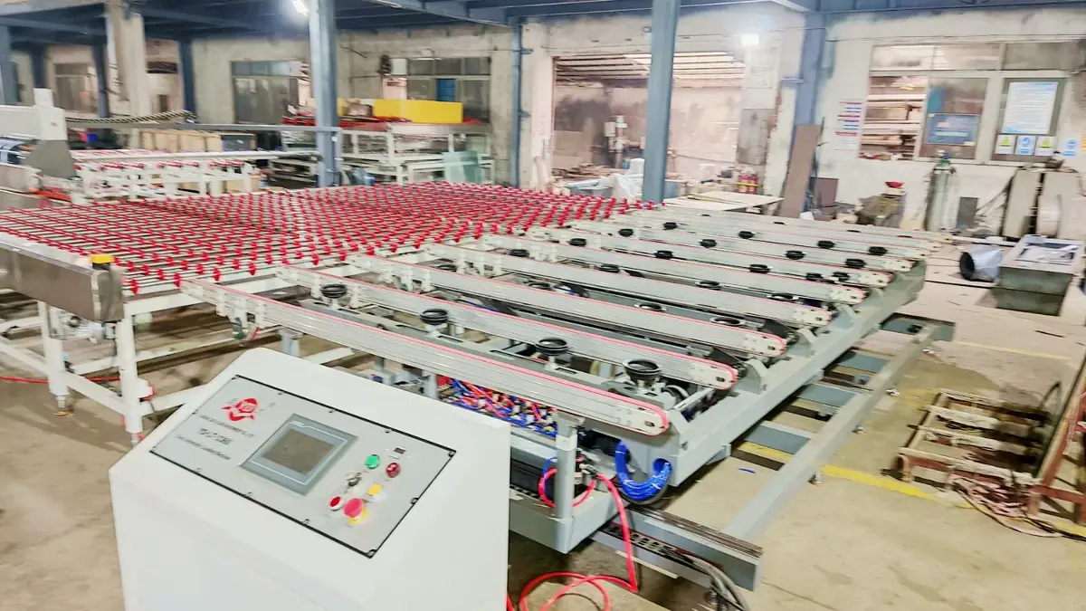
This digital handshake prevents collisions and eliminates dead time between processing cycles. The touchscreen allows the operator to input the exact dimensions and thickness of the current batch. The PLC then calculates the optimal tilt speed and feed rate for that specific glass geometry.
Once the glass transitions from the suction cups to the transport bed, a different mechanical system takes over. The extensive conveyor system relies on precise roller alignment to move the glass forward.
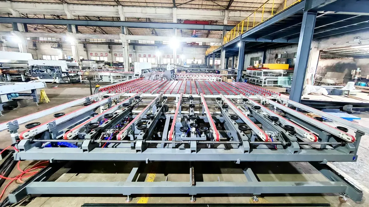
These rollers are typically coated in specific durometer materials to avoid scratching sensitive low-emissivity coatings. The transfer from the static drop-off point to the moving conveyor must occur without any lateral dragging. The machine lowers the glass exactly parallel to the roller plane, ensuring perfectly aligned entry into the washing or edging equipment.
Structural Engineering and Frame Rigidity
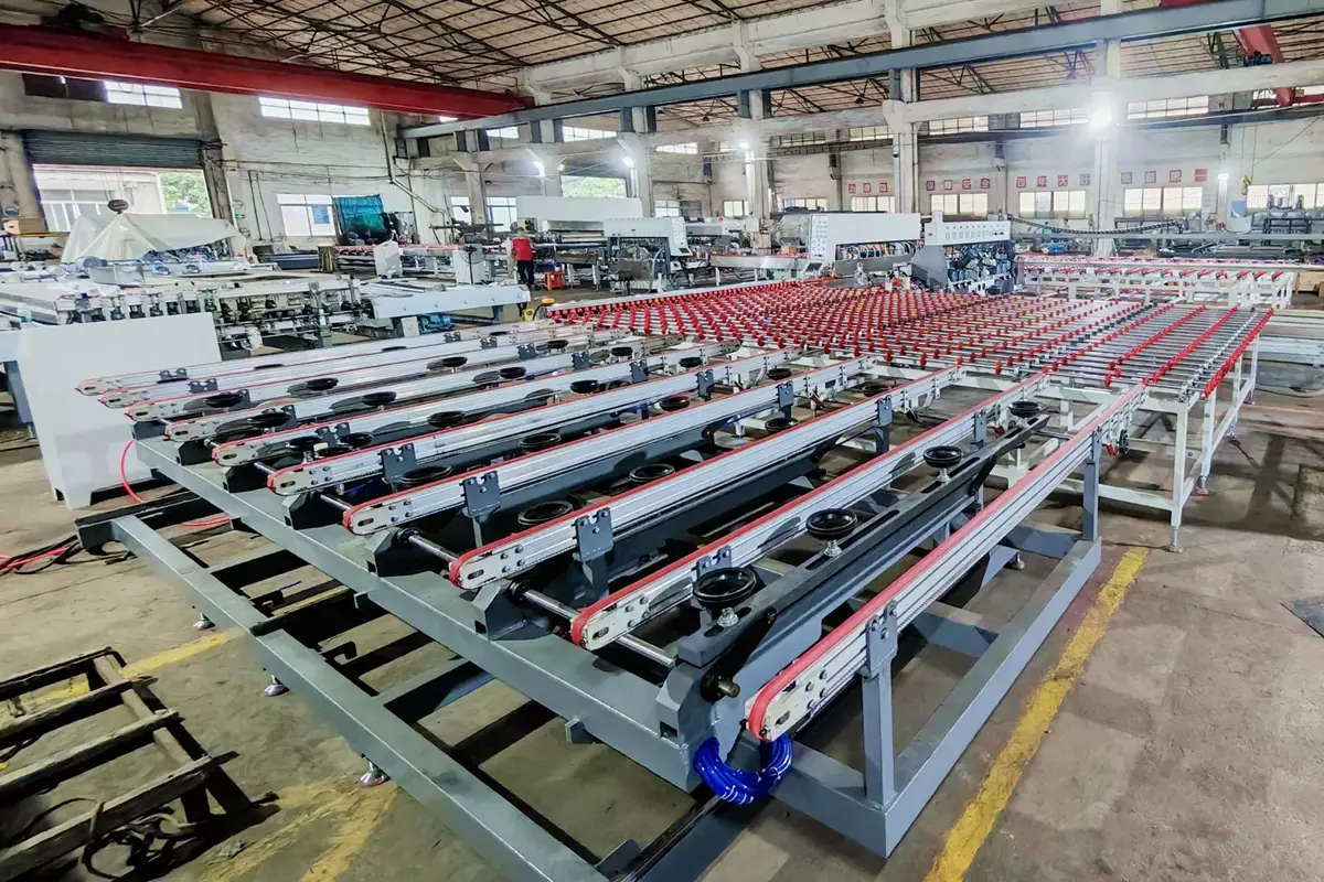
The physical footprint of the machine dictates its stability during heavy lifting cycles. Outer dimensions vary significantly based on the chosen model, ranging from 3000 by 2200 millimeters up to 6000 by 3500 millimeters. The base height remains a standard 900 millimeters to match standard processing line elevations.
This robust white powder-coated frame is engineered to resist torsional twisting. When an asymmetric load is applied, such as lifting a narrow but heavy panel on one side, the frame must not warp. Even a few millimeters of chassis flex would misalign the glass as it enters the double edging machine.
For us, operating as a high-tech manufacturing entity in Foshan since the 1990s, observing equipment behavior over 30 years of operations has highlighted the necessity of structural rigidity. Equipment longevity is entirely dependent on how well the base frame manages cyclical mechanical stress over millions of repetitions.
The pneumatic hoses and mechanical joints are routed carefully within this frame. This protects the sensitive air lines from falling glass shards or accidental impact from forklifts operating nearby. Every mechanical joint requires regular lubrication, and the open-frame design allows maintenance teams easy access to these critical wear points.
Technical Specifications Matrix
Evaluating the right equipment requires matching the mechanical capabilities to your specific factory throughput. The table below outlines the core engineering parameters across different machine configurations.
| Specification Parameter | Technical Range / Detail |
|---|---|
| Model Variants | YD-LT-3360, YD-LT-2442, YD-LT-2536, YD-LT-2030 |
| Maximum Glass Dimensions | 3300×6000mm down to 2000×3000mm |
| Minimum Glass Dimensions | 800×1000mm down to 500×600mm |
| Supported Thickness Range | 3mm to 19mm |
| Lifting Arm Configuration | 5 or 7 independent articulated arms |
| Vacuum Interface | 3 or 4 suction cups per lifting arm |
| Power Consumption | 7.5 kW steady state |
| Kinetic Cycle Speed | 3 to 6 pieces per minute |
| Physical Footprint (L×W×H) | 6000×3500×900mm down to 3000×2200×900mm |
These parameters dictate the operational boundaries of the loading sequence. Exceeding the maximum glass size or weight limits fundamentally compromises the vacuum hold and the hydraulic lifting capacity.
Redefining Factory Floor Safety Protocols
Manual handling of large glass panels inherently exposes workers to severe laceration and crushing hazards. The sharp edges of raw cut float glass can easily slice through standard protective gear during a slip or fall. Automation removes the human element from this immediate drop zone entirely.
A sudden change in factory humidity or temperature can make glass surfaces slippery and difficult for operators to grip. The pneumatic suction cups bypass this environmental variable, establishing a secure mechanical lock regardless of surface condensation.
By utilizing advanced glass machinery, facilities drastically reduce their liability and insurance premiums. The equipment does not fatigue at the end of a long shift, which is historically when the majority of handling accidents occur. Consistent mechanical execution protects both the raw materials and the workforce.
Frequently Asked Technical Questions
Does a higher working speed compromise the vacuum grip during the initial lift?
The cycle speed of 3 to 6 pieces per minute is specifically governed by the PLC to prevent grip failure. The machine applies full vacuum pressure before the lifting arms engage their upward motion. The acceleration curve is mathematically mapped to remain well below the shear force limit of the suction cups, ensuring the glass never slips during transit.
How does the system physically adapt when switching from 3mm to 19mm glass thickness?
The physical suction cups remain the same, but the operator must adjust the PLC parameters. For 19mm glass, the system utilizes maximum vacuum pressure and a slower, higher-torque lifting profile to manage the weight. For 3mm glass, the lift speed can increase, but the system must carefully balance the drop-off sequence to prevent the thin sheet from flexing or snapping upon contacting the conveyor rollers.
Can the loading arms handle glass pieces smaller than the specified minimum of 500x600mm?
Attempting to load pieces smaller than the engineered minimum causes two structural problems. First, the glass will not physically span across enough suction cups to trigger the minimum vacuum seal required by the safety sensors. Second, small pieces will fall through the gaps between the conveyor rollers once placed on the horizontal bed.
Evaluating Deployment in High-Volume Operations
Different manufacturing sectors demand completely different loading strategies. Construction glass processing involves handling massive, heavy panels destined for commercial facades. Here, the priority is absolute stability and managing the extreme weight of 19-millimeter architectural substrates.
Furniture glass manufacturing operates on a different rhythm. These facilities process smaller, thinner pieces but require a much higher frequency of movement. The loading equipment must pivot quickly, picking and placing panels rapidly without inducing stress fractures in the 3-millimeter glass.
Home furnishing and mirror production lines sit somewhere in the middle. They require the machine to handle highly sensitive surface coatings. The vacuum cups must be meticulously maintained to ensure they do not leave permanent rings or chemical residue on the treated glass surfaces.
Facilities must calculate their return on investment by measuring the reduction in broken materials. A single dropped 3300 by 6000-millimeter panel represents a significant financial loss, not just in raw material, but in lost processing time. The 7.5-kilowatt power draw is a negligible operational cost compared to the labor savings.
Properly implemented glass machinery fundamentally shifts a factory from a reactive environment to a predictable production engine. Managing the flow of raw materials with rigid automation allows plant managers to schedule complex processing tasks with absolute confidence.
CONTACT US


LIAODA (LAD) Glass Machinery Co., Ltd.
We are always providing our customers with reliable products and considerate services.
If you would like to keep touch with us directly, please go to contact us
-
![Home]()
Home
-
![Tel]()
Tel
-
![Email]()
Email
-
Share
-
![Contact]()
Contact


